Introduzione:
Saldatura di giunti d'angolo è una delle tecniche più essenziali e ampiamente utilizzate nella fabbricazione dei metalli e nell'assemblaggio strutturale. Dalla costruzione di telai in acciaio e dalla produzione di serbatoi di stoccaggio alla realizzazione di attrezzature industriali e strutture architettoniche, questo metodo si trova in innumerevoli applicazioni in praticamente ogni settore. Nonostante la sua presenza comune nelle officine e nei cantieri, una tecnica corretta, una chiara comprensione della geometria del giunto e la conoscenza di come i diversi processi influenzino il risultato finale sono fondamentali. Una saldatura eseguita male può compromettere l'integrità di un'intera struttura, mentre un giunto formato correttamente offre eccellente resistenza, rigidità e durata.
Questa guida completa copre tutto ciò che devi sapere sulla saldatura di giunti d'angolo—dalla definizione di base dei giunti d'angolo, alle tecniche passo dopo passo per eseguire la saldatura, alle posizioni di partenza, al confronto della resistenza tra i tipi di giunti, alle tre principali categorie di giunti saldati e ai cinque processi di saldatura di base. Che tu sia un principiante che impara il mestiere, un fabbro professionista che cerca di affinare le proprie competenze o un ingegnere che progetta strutture saldate, questa guida fornisce le conoscenze pratiche necessarie per applicazioni di successo.
Cosa sono i giunti d'angolo nella saldatura?
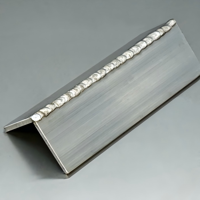
Capire cosa sono i giunti d'angolo nella saldatura è il punto di partenza essenziale per padroneggiare questa tecnica. Un giunto d'angolo si forma quando due pezzi di metallo si incontrano ad angolo, creando una configurazione a forma di L. Questo è uno dei tipi di giunto più comuni nella saldatura ed è ampiamente utilizzato nella costruzione di telai, assemblaggi di scatole, involucri e applicazioni strutturali. In un giunto d'angolo, i bordi dei due pezzi si uniscono in un angolo, con le superfici tipicamente perpendicolari tra loro, somigliando all'angolo di una cornice o di una scatola rettangolare. Il processo utilizzato per unire questi pezzi determina direttamente le prestazioni strutturali del giunto.
I giunti d'angolo sono distinti dagli altri tipi di giunti a causa della loro geometria. A differenza di un giunto di testa dove due pezzi sono allineati bordo contro bordo sullo stesso piano, o di un giunto a T dove un pezzo si trova perpendicolare al centro di un altro, i giunti d'angolo presentano due pezzi che si incontrano ai loro bordi per formare un angolo esterno. Le tecniche per questa geometria devono tenere conto della sua forma unica per ottenere una fusione e una penetrazione adeguate. Questi giunti sono classificati in diverse varianti in base a come vengono preparati i bordi, e ogni variante influisce su come il processo dovrebbe essere eseguito:
Giunto d'angolo chiuso: Entrambi i bordi si incontrano perpendicolarmente senza alcuno spazio o smusso. I bordi si accostano l'uno all'altro ad angolo retto, formando un angolo stretto di 90 gradi. Questa è la forma più semplice ed è comunemente utilizzata su materiali più sottili dove la penetrazione completa non è critica.
Giunto d'angolo aperto: Un piccolo spazio viene intenzionalmente lasciato tra i due bordi. Questo spazio consente una migliore penetrazione nella radice del giunto ed è spesso utilizzato quando si uniscono sezioni più spesse dove è richiesta una fusione completa.
Giunto d'angolo semiaperto: Un bordo viene smussato mentre l'altro rimane quadrato. Questa preparazione fornisce un equilibrio tra facilità di assemblaggio e capacità di penetrazione, rendendo il processo più efficace su materiali di spessore medio.
Giunto d'angolo flangiato: Uno o entrambi i bordi vengono piegati verso l'esterno per creare una flangia, che funge quindi da superficie di saldatura. Questo è comune nelle applicazioni di lamiera dove l'obiettivo è creare bordi puliti e finiti.
Questo tipo di giunto è ampiamente utilizzato perché fornisce un aspetto pulito e professionale ed è relativamente facile da assemblare rispetto a geometrie più complesse. Tuttavia, presenta sfide uniche—l'accesso a entrambi i lati del giunto può essere limitato, la distribuzione del calore può essere irregolare e il controllo della distorsione richiede una tecnica attenta. Un'esecuzione corretta richiede attenzione a questi fattori per ottenere risultati costanti e di alta qualità.
Nelle applicazioni pratiche, i giunti d'angolo si trovano in innumerevoli prodotti: i telai delle macchine, gli angoli dei contenitori di stoccaggio, i bordi degli involucri elettronici, gli elementi strutturali degli edifici e i telai dei veicoli. La padronanza di questa tecnica è quindi essenziale per qualsiasi fabbro che lavori con componenti strutturali o in lamiera.
Come eseguire una saldatura d'angolo:
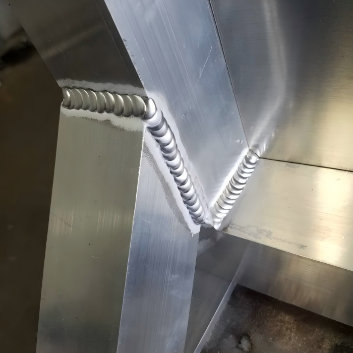
Imparare a eseguire correttamente una saldatura d'angolo è un'abilità che si sviluppa attraverso la comprensione, la pratica e l'attenzione ai dettagli. La saldatura di giunti d'angolo può essere eseguita utilizzando vari processi—MIG, TIG, a elettrodo e persino con filo animato—ma le tecniche e i principi fondamentali rimangono coerenti in tutti i metodi. Questa sezione fornisce una guida completa passo dopo passo alla saldatura di giunti d'angolo che si applica indipendentemente dal processo di saldatura specifico che stai utilizzando.
Passo 1: Preparazione del giunto
Una preparazione adeguata è la base per una saldatura di giunti d'angolo di successo. Inizia pulendo accuratamente le superfici da saldare. Rimuovi tutto olio, grasso, vernice, ruggine e altri contaminanti usando uno sgrassatore, una spazzola metallica o una smerigliatrice. La pulizia del materiale influisce direttamente sulla qualità della saldatura dei giunti d'angolo—i contaminanti creano porosità, riducono la resistenza e possono portare a cricche. Per la saldatura di giunti d'angolo, presta particolare attenzione ai bordi che formeranno il giunto. Se il materiale ha scaglie di laminazione o ossidazione pesante, usa una smerigliatrice con disco a lamelle o mola abrasiva per esporre metallo pulito e brillante prima di iniziare il processo di saldatura del giunto d'angolo.
Successivamente, determina se il giunto d'angolo richiede una preparazione dei bordi come la smussatura. Per materiali sottili (tipicamente sotto i 3 mm), un semplice bordo quadrato è spesso sufficiente per la saldatura di giunti d'angolo. Per materiali più spessi, smussare uno o entrambi i bordi crea una scanalatura che consente una penetrazione più profonda e una migliore fusione durante la saldatura del giunto d'angolo. L'angolo di smusso varia tipicamente da 30 a 45 gradi per lato, a seconda dello spessore del materiale e della resistenza di saldatura richiesta.
Passo 2: Assemblaggio e posizionamento del giunto
La preparazione dell'assemblaggio è fondamentale nella saldatura di giunti d'angolo. Posizionare i due pezzi in modo che formino l'angolo desiderato, comunemente 90 gradi. Utilizzare squadre, angolari o morsetti magnetici per mantenere i pezzi saldamente all'angolo corretto. Assicurarsi che i bordi siano allineati a filo tra loro. Se i pezzi sono sfalsati o disallineati, la saldatura del giunto d'angolo risulterà irregolare e strutturalmente compromessa. Una corretta preparazione dell'assemblaggio è uno dei fattori più importanti per una saldatura di giunti d'angolo riuscita.
La posizione di saldatura per il giunto d'angolo dipende dall'orientamento del pezzo. La saldatura del giunto d'angolo può essere eseguita in posizione piana (saldatura orizzontale, pezzi verticali), posizione orizzontale (saldatura lungo un asse orizzontale), posizione verticale (saldatura verso l'alto o verso il basso) o posizione sopratesta. La posizione piana è la più facile e produttiva per la saldatura di giunti d'angolo, mentre la saldatura sopratesta è la più impegnativa e richiede maggiore abilità ed esperienza.
Passo 3: Saldatura di puntatura
La saldatura di puntatura è un passaggio preliminare essenziale nella saldatura di giunti d'angolo. Eseguire piccole puntature a intervalli lungo il giunto, tipicamente alle estremità e ogni 25-50 mm lungo la lunghezza per giunti più lunghi. Queste puntature mantengono i pezzi in posizione durante la passata finale di saldatura del giunto d'angolo e prevengono movimenti causati da dilatazione e contrazione termica. Per la saldatura di giunti d'angolo, le puntature dovrebbero essere posizionate su entrambi i lati dell'angolo se accessibili, o solo sull'angolo esterno se l'accesso è limitato. Assicurarsi che le puntature siano sufficientemente resistenti per mantenere i pezzi ma non così grandi da interferire con l'operazione finale di saldatura del giunto d'angolo.
Passo 4: Selezione del processo e dei parametri di saldatura
Scegliere il processo di saldatura appropriato per la propria applicazione di saldatura di giunti d'angolo. La saldatura MIG è spesso preferita per la saldatura di giunti d'angolo di acciaio e alluminio grazie alla sua velocità e facilità d'uso. La saldatura TIG offre un controllo superiore ed è ideale per la saldatura di giunti d'angolo di materiali sottili, acciaio inossidabile o applicazioni che richiedono un aspetto pulito e senza schizzi. La saldatura a elettrodo è adatta per la saldatura strutturale pesante di giunti d'angolo, particolarmente in condizioni esterne o ventose dove la protezione gassosa è impraticabile per la saldatura di giunti d'angolo.
Impostare i parametri di saldatura in base al tipo di materiale, allo spessore e alla configurazione del giunto. Per la saldatura MIG di giunti d'angolo in acciaio al carbonio, le impostazioni tipiche potrebbero includere 18-22 volt, velocità di avanzamento del filo di 200-300 pollici al minuto e gas di protezione argon/CO₂ 75/25 a 20-30 CFH. Per la saldatura TIG di giunti d'angolo, l'amperaggio tipico potrebbe variare da 70 a 150 ampere a seconda dello spessore, con protezione di argon al 100% a 15-20 CFH. La corretta selezione dei parametri è essenziale per una saldatura di giunti d'angolo di qualità.
Passo 5: Esecuzione della saldatura d'angolo
Quando si esegue la saldatura di giunti d'angolo, la tecnica varia a seconda che si saldi dall'angolo esterno, dall'angolo interno o da entrambi.
Per una saldatura sull'angolo esterno (saldatura sull'angolo esterno): Tenere la pistola o la torcia a un angolo di 45 gradi rispetto a entrambi i pezzi, bisecando l'angolo. Utilizzare un leggero angolo di spinta o trascinamento di 5-15 gradi a seconda del processo. Per la saldatura MIG di giunti d'angolo, un angolo di spinta (puntando l'ugello nella direzione di avanzamento) fornisce una migliore copertura del gas e un profilo del cordone più piatto. Muovere la torcia di saldatura lungo il giunto a velocità costante, mantenendo una lunghezza d'arco stabile. Osservare attentamente il bagno di saldatura: dovrebbe bagnare uniformemente entrambe le superfici dell'angolo. Una saldatura di giunti d'angolo riuscita dipende dal mantenimento di questo equilibrio.
Per una saldatura sull'angolo interno (saldatura sull'angolo interno, nota anche come saldatura a cordone d'angolo su un giunto d'angolo): Posizionare la torcia in modo che punti nell'angolo, mantenendo un angolo di 45 gradi rispetto a entrambe le superfici. Questo è simile alla saldatura di un cordone d'angolo su un giunto a T. L'angolo della torcia dovrebbe essere di circa 45 gradi rispetto alle superfici verticale e orizzontale, con una leggera inclinazione nella direzione di avanzamento. La saldatura di giunti d'angolo interni richiede spesso un controllo del calore più attento rispetto alla saldatura di giunti d'angolo esterni.
Per entrambi i tipi di saldatura di giunti d'angolo, utilizzare una tecnica di tessitura se necessario per distribuire il calore e garantire una corretta fusione su entrambi i lati. Una leggera oscillazione laterale della torcia può aiutare il bagno di saldatura a coprire entrambi i pezzi in modo uniforme. La chiave per una saldatura di giunti d'angolo riuscita è mantenere un angolo della torcia e una velocità di avanzamento costanti lungo tutto il giunto.
Passo 6: Ispezione post-saldatura e pulizia
Dopo aver completato la saldatura del giunto d'angolo, lasciare raffreddare il giunto naturalmente. Rimuovere eventuali schizzi o scorie utilizzando un martello da scorie, una spazzola metallica o una smerigliatrice. Ispezionare visivamente il risultato della saldatura del giunto d'angolo per difetti come sottosquadri, mancanza di fusione, porosità o cricche. Per applicazioni critiche, considerare test non distruttivi come l'ispezione con liquidi penetranti o l'ispezione con particelle magnetiche per verificare la qualità del proprio lavoro di saldatura di giunti d'angolo.
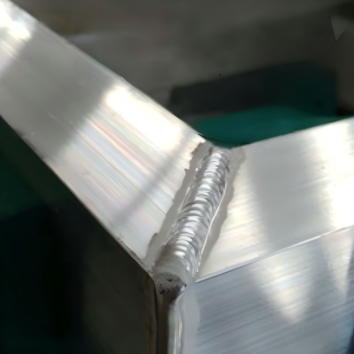
Quali sono i tre tipi di giunti saldati?
Comprendere i tre tipi principali di giunti saldati è fondamentale per chiunque lavori nella fabbricazione. Sebbene l'American Welding Society (AWS) riconosca cinque tipi di giunti di base, i tre più comunemente incontrati nella saldatura quotidiana sono: Giunti di testa, Giunti a T e Giunti d'angolo. Questa sezione si concentra su questi tre, con la saldatura di giunti d'angolo come parte centrale della discussione. I restanti due tipi di giunti—giunti a sovrapposizione e giunti di bordo—sono trattati come informazioni supplementari nella sezione successiva.
Giunto di testa
Un giunto di testa si forma quando due pezzi sono posizionati bordo contro bordo sullo stesso piano. Questo è il tipo di giunto più semplice ed è comunemente utilizzato per unire piastre, lamiere e tubi testa a testa. Il vantaggio principale del giunto di testa è che crea una superficie continua senza materiale sovrapposto, rendendolo ideale per applicazioni in cui è richiesta una superficie liscia e a filo, come nella saldatura di tubi, nell'unione di lamiere e nelle connessioni strutturali.
Giunti di testa possono essere preparate in vari modi a seconda dello spessore del materiale: a bordo quadrato (senza preparazione dei bordi, per sezioni sottili), a V (smusso singolo su ciascun pezzo), a U o a doppia V per sezioni più spesse. Le saldature di testa a piena penetrazione raggiungono una resistenza pari al materiale base, rendendole una delle configurazioni di giunto più resistenti disponibili. I giunti di testa richiedono un allineamento e un accoppiamento precisi per evitare spazi vuoti, e sono più difficili da saldare rispetto ai giunti d'angolo o ai giunti a T perché l'accesso alla radice è critico.
Giunto a T (Giunto a T)
Un giunto a T si verifica quando un pezzo è posizionato perpendicolarmente alla superficie di un altro, formando una forma a T. Questo è un tipo di giunto molto comune nella costruzione strutturale in acciaio, nei telai di macchinari e nella produzione di attrezzature. I giunti a T sono tipicamente saldati utilizzando saldature d'angolo su uno o entrambi i lati dell'elemento verticale.
Giunti a T sono relativamente facili da preparare e saldare perché il pezzo fornisce una superficie stabile per la torcia di saldatura. La dimensione della saldatura può essere facilmente aumentata per fornire resistenza aggiuntiva, e il giunto si adatta naturalmente alle saldature d'angolo, che sono tolleranti e resistenti alle cricche. I giunti a T sono eccellenti per applicazioni portanti perché il trasferimento del carico è semplice e il giunto può essere rinforzato con grandi dimensioni di saldatura. Per la massima resistenza, i giunti a T sono saldati su entrambi i lati, creando di fatto una saldatura d'angolo doppia.
Giunto d'angolo
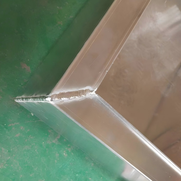
Come discusso in precedenza, un giunto d'angolo si forma quando due pezzi si incontrano con un angolo di 90 gradi, creando una forma a L. La saldatura del giunto d'angolo è il processo utilizzato per unire questi pezzi. I giunti d'angolo sono comunemente usati per costruire strutture rettangolari, scatole, telai e involucri. A seconda dell'accesso e dello spessore, i giunti d'angolo possono essere saldati dall'esterno, dall'interno o da entrambi i lati attraverso varie tecniche di saldatura del giunto d'angolo.
I giunti d'angolo sono apprezzati per il loro aspetto pulito e la semplicità geometrica. Sono particolarmente popolari nella fabbricazione di lamiere perché le superfici piane dei pezzi consentono un facile setup e serraggio. Tuttavia, i giunti d'angolo sono meno tolleranti dei giunti a T se si verifica distorsione: l'angolo di 90 gradi deve essere mantenuto con precisione per garantire un corretto assemblaggio. Per applicazioni strutturali, i giunti d'angolo saldati su entrambi i lati (ottenuti tramite saldatura del giunto d'angolo sia all'esterno che all'interno) forniscono una resistenza significativamente maggiore rispetto alle saldature d'angolo su un solo lato. Una corretta tecnica di saldatura del giunto d'angolo è essenziale per ottenere la resistenza desiderata in questi giunti.
Quali sono i 5 processi fondamentali di saldatura?
Comprendere i cinque processi fondamentali di saldatura è essenziale per selezionare il metodo giusto per la tua applicazione di saldatura del giunto d'angolo. Ogni processo ha caratteristiche distinte che lo rendono adatto a diversi materiali, spessori e condizioni di lavoro. Sebbene esistano molti processi di saldatura, i cinque più fondamentali e ampiamente utilizzati sono: SMAW (elettrodo rivestito), GMAW (MIG), GTAW (TIG), FCAW (anima flussata) e SAW (saldatura ad arco sommerso). Ciascuno può essere applicato alla saldatura del giunto d'angolo con risultati diversi.
SMAW – Saldatura ad arco con elettrodo rivestito (saldatura a bastone)
SMAW è il processo di saldatura più antico e tradizionale. Utilizza un elettrodo consumabile rivestito di flusso, che brucia per produrre un gas di protezione e una scoria che copre la saldatura. La saldatura a bastone è estremamente versatile, funziona all'aperto con vento e può essere utilizzata su materiali sporchi o arrugginiti. Per la saldatura del giunto d'angolo, la saldatura a bastone è comunemente usata per acciaio strutturale pesante, fabbricazione in cantiere e lavori di riparazione. Il processo è più lento del MIG ma non richiede gas di protezione esterno, rendendolo una scelta pratica per la saldatura del giunto d'angolo in località remote.
GMAW – Saldatura ad arco con gas metallo (saldatura MIG)
Saldatura MIG utilizza un elettrodo a filo solido alimentato continuamente e un gas di protezione esterno, tipicamente una miscela di argon e anidride carbonica. Questo processo è veloce, pulito e relativamente facile da imparare. La saldatura MIG è una delle scelte più popolari per la saldatura del giunto d'angolo in ambienti di produzione grazie ai suoi alti tassi di deposizione e all'eccellente aspetto della saldatura. Il MIG funziona bene su acciaio al carbonio, acciaio inossidabile e alluminio. Per la saldatura del giunto d'angolo, il MIG fornisce una buona penetrazione e livelli gestibili di spruzzi, rendendolo una scelta affidabile per la maggior parte dei lavori di fabbricazione.
GTAW – Saldatura ad arco con tungsteno e gas (saldatura TIG)
Saldatura TIG utilizza un elettrodo di tungsteno non consumabile e una barra d'apporto separata, con gas di protezione argon o elio. Questo processo fornisce un controllo eccezionale sull'apporto di calore e sul posizionamento del metallo di saldatura. La saldatura TIG è ideale per la saldatura del giunto d'angolo su materiali sottili, acciaio inossidabile, alluminio e titanio dove l'aspetto della saldatura è critico. Il processo produce risultati di saldatura del giunto d'angolo puliti e senza spruzzi con un'eccellente qualità estetica. Tuttavia, il TIG è più lento e richiede più abilità del MIG o della saldatura a bastone, rendendolo più adatto per applicazioni di saldatura del giunto d'angolo di precisione.
FCAW – Saldatura ad arco con anima flussata
FCAW è simile al MIG ma utilizza un filo tubolare riempito di flusso. Può essere autoprotetto (senza gas esterno richiesto) o protetto da gas. Questo processo offre alti tassi di deposizione e un'eccellente penetrazione, rendendolo adatto per la saldatura del giunto d'angolo su sezioni spesse. FCAW è comunemente usato nella produzione di attrezzature pesanti, nell'edilizia e nella cantieristica navale. Sebbene produca più spruzzi e fumo del MIG, offre una buona tolleranza al vento e ai contaminanti superficiali, rendendolo un'opzione praticabile per la saldatura del giunto d'angolo all'aperto.
SAW – Saldatura ad arco sommerso
SAW è un processo meccanizzato in cui l'arco è sommerso sotto un manto di flusso granulare. Offre tassi di deposizione eccezionalmente elevati e penetrazione profonda, producendo saldature di alta qualità con abilità minima dell'operatore. SAW è utilizzato per acciaio strutturale pesante, recipienti a pressione e saldatura di giunti lunghi. Sebbene non sia comunemente usato per la saldatura del giunto d'angolo in applicazioni manuali, SAW può essere impiegato nella saldatura automatizzata del giunto d'angolo di sezioni di acciaio spesse, come giunti d'angolo in grandi serbatoi o nella fabbricazione di travi strutturali.
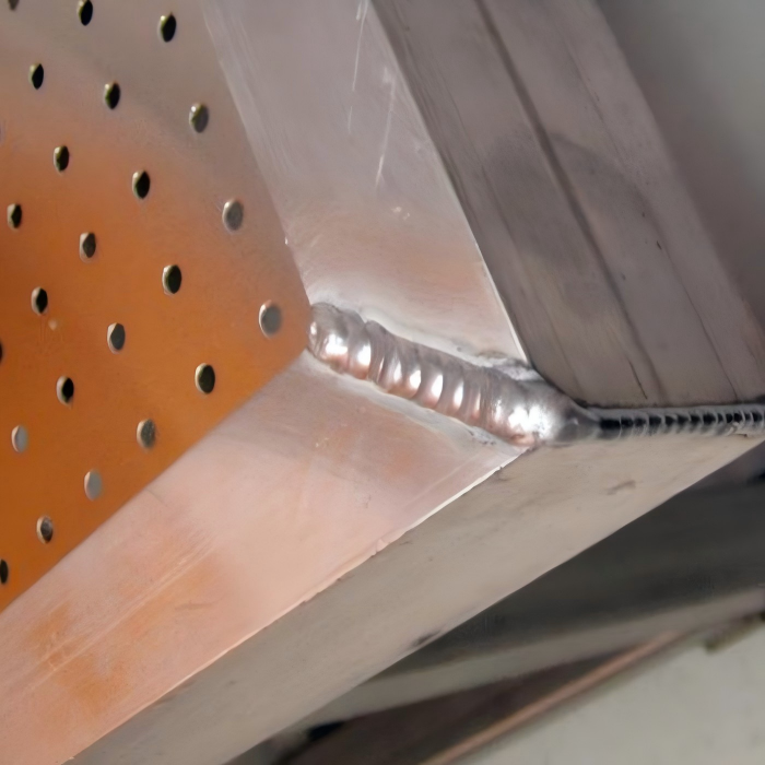
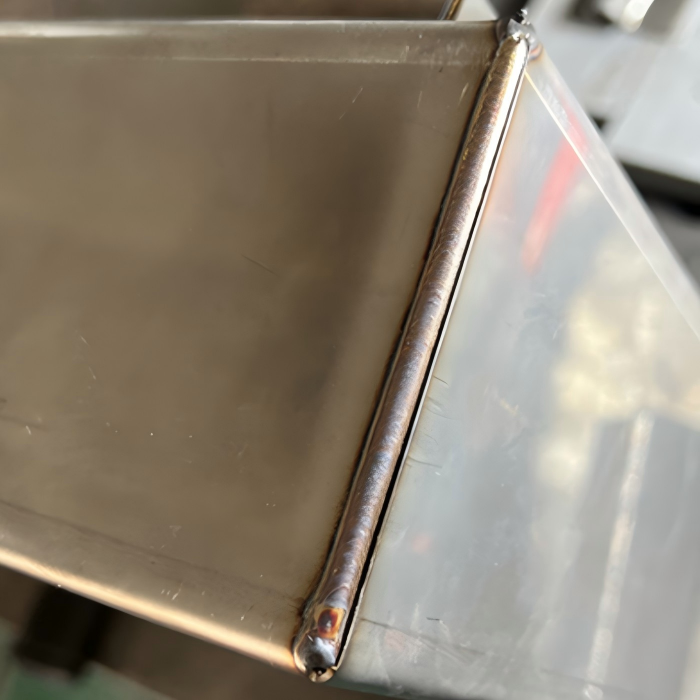
Consigli pratici per una saldatura d'angolo di successo:
Per massimizzare il successo nelle applicazioni di saldatura d'angolo, tieni a mente questi consigli pratici:
- Usa un fissaggio adeguato: Serra o imbastisci saldamente i giunti d'angolo per mantenere l'angolo di 90 gradi. La distorsione è il problema più comune nella saldatura d'angolo, e un buon fissaggio è la contromisura più efficace.
- Controlla l'apporto di calore: Usa saldatura intermittente o tecniche a ritroso su giunti d'angolo lunghi per prevenire surriscaldamento e distorsione durante la saldatura d'angolo.
- Mantieni una velocità di avanzamento costante: Una velocità di avanzamento irregolare crea variazioni nella penetrazione e nella dimensione della saldatura nella saldatura d'angolo. Esercitati a mantenere un ritmo costante.
- Osserva il bagno di saldatura: Concentra l'attenzione sul bagno fuso, non sull'arco, durante la saldatura d'angolo. Il bagno di saldatura ti informa su penetrazione, fusione e problemi di contaminazione.
- Usa il gas di protezione corretto: Per la saldatura d'angolo MIG dell'acciaio, usa una miscela 75/25 argon-CO₂. Per la saldatura d'angolo TIG, usa argon 100%.
- Pulisci accuratamente tra le passate: Se saldi un giunto d'angolo spesso con più passate, rimuovi scorie e strati di ossido prima di applicare le passate successive.
- Ispeziona il tuo lavoro: Controlla la presenza di sottosquadri, mancata fusione e l'angolo corretto dopo la saldatura d'angolo.