For the aluminum welding with tig, you have seen it hundreds of times.
A beautiful robotic welding cell. Perfectly programmed paths. Consistent travel speeds.
Yet, the weld comes out looking like someone rubbed charcoal all over it.
Black. Sooty. Dirty.
Meanwhile, the manual welder on the other side of the shop runs a bead on the exact same aluminum part—and it comes out shiny and silver.
As a manufacturing engineer, this discrepancy drives you crazy. You are not a welder. You are a problem solver. But this black soot problem keeps coming back.
Here is the truth: Black soot on aluminum welds is not a mystery. It is physics. And once you understand the science, you can fix it permanently.
In this guide, we will break down exactly why aluminum turns black during welding, why robotic cells are more prone to this issue, and provide engineering-level solutions you can implement today.
What Is That Black Stuff Anyway? (A Manufacturing Engineer’s Explanation)
Let us start with the science.
The black residue is NOT:
· Carbon from contamination
· Burnt aluminum
· Dirt or oil residue
The black residue IS:
· Aluminum Oxide (Al²O³) and Magnesium Oxide (MgO)
· Microscopic particles of vaporized metal that oxidized in the air
· A clear indicator of failed gas coverage
Here is what happens inside the arc:
1. The arc temperature reaches approximately 10,000°F (5,500°C) .
2. Aluminum boils at 4,479°F (2,470°C) . Magnesium boils even lower at 1,994°F (1,090°C) .
3. The arc vaporizes the metal at the front of the weld pool.
4. This metal vapor rises upward.
5. If the vapor touches oxygen (even for a fraction of a second), it instantly oxidizes into black or gray powder.
The takeaway: Black soot = unprotected metal vapor. No exceptions for aluminum welding with tig.

Custom Aluminum Welding with Tig Parts from Flow Wing!
Why Does This Happen More Often in Robotic Welding (aluminum welding with tig)?
This is where many manufacturing engineers get frustrated.
You programmed the robot correctly. The path is smooth. The speeds are optimized.
But the robot still produces black welds while the manual welder does not.
Here are the real reasons:
1. The “Dead” Torch Angle (Push vs. Drag)
Variable Manual Welder Robotic Welding (Common)
Torch angle 10-15° Push (instinctive) 0° (perpendicular) or Drag
Result Gas blanket pushes air away Venturi effect sucks air into shield
The science: When you drag a torch or hold it perpendicular, you create a low-pressure zone at the front of the weld pool. This acts like a vacuum, pulling surrounding air into the argon shield. Air + vapor = black soot.
Why manual welders avoid this: They cannot see the puddle clearly with a drag angle. So they naturally push. The robot has no such instinct.
2. Contact Tip to Work Distance (CTWD) Drift
The manual welder: Keeps the nozzle within ½ inch (12mm) of the workpiece. If the distance increases, they feel it and adjust immediately.
The robot: Follows a rigid path. If your fixture is warped, or the part is not clamped perfectly, the torch drifts away. At ¾ inch, the gas shield becomes turbulent. At 1 inch, it is useless.
The result: Metal vapor rises, hits open air, oxidizes, and turns black.

3. Constant Heat Input (No Adaptation)
The manual welder: A skilled welder watches the puddle. If it gets too hot, they move faster. If it is too cold, they pause. They adapt second by second.
The robot: Most robotic programs run constant voltage (CV) or constant current (CC) with fixed travel speeds. No adaptation. No feedback.
The problem: Aluminum’s thermal conductivity is extremely high—about 4x higher than steel. Heat disappears instantly into the workpiece. A parameter that works at the start of a weld may overheat the part by the end.
Overheating = more metal vapor = more black soot.
Custom Aluminum Welding with Tig Parts from Flow Wing!
The Manufacturing Engineer’s Pain Points (Real Problems You Face):
Let us be honest. You already know the basics.
Here are the real frustrations that keep you up at night:
Pain Point #1: “My robot program works perfectly… until it doesn’t.”
You validated the program. The first 10 parts passed inspection. Then part #11 comes out black.
The hidden cause: Aluminum parts warp under heat. A fixture that worked for the first 10 parts may shift on part #11. The robot does not know this. It follows the same path, but the part moved.
Pain Point #2: “I am a programmer, not a welder.”
You understand robots. You understand code. But you never learned how to read a weld puddle.
The reality: Welding aluminum requires process knowledge that most engineering programs do not teach. You are expected to solve a problem without the fundamental training.
Pain Point #3: “The shift supervisor blames the robot. But the robot is fine.”
When welds turn black, the easy answer is “the robot is broken.”
But 90% of the time, the robot is doing exactly what it was told. The problem is the program or the process—not the machine.
Pain Point #4: “Fixing one problem creates another.”
You increase gas flow to fix the black soot. Now you get tungsten erosion or arc instability.
You change torch angle. Now the robot crashes into the fixture.
You slow down travel speed. Now the heat-affected zone (HAZ) is too wide and the part fails tensile testing.
The frustration: Aluminum welding with tig is a system of trade-offs. Changing one variable affects five others.
Custom Aluminum Welding with Tig Parts from Flow Wing!
Solutions: How to Eliminate Black Soot from Your Robotic Aluminum Welds
Now for the part you actually want: actionable engineering solutions for custom aluminum welding with Tig parts.
Here is a step-by-step playbook.

Solution #1: Fix the Torch Angle (Program Push, Not Drag)
This is the single highest-impact change you can make.
Action item: Open your robot teach pendant. Review every weld path.
| If you see… | Change to… |
| Perpendicular torch (0°) | 10-15° Push angle |
| Drag angle (negative) | 10-15° Push angle |
Verification: Run a test bead on a flat plate. If the weld comes out black, your angle is still wrong. Keep adjusting until you see silver.
Solution #2: Shorten and Stabilize CTWD
Target: Contact Tip to Work Distance = 12-15mm (½ inch maximum)
Action items:
1. Measure your current CTWD on every weld path.
2. Reprogram any path where CTWD exceeds 15mm.
3. Inspect your fixtures. If they are warped, repair or replace them.
4. Consider through-arc seam tracking (TAST) for parts with inconsistent fit-up.
Pro tip: A gas lens (sieve) allows you to increase CTWD slightly without losing gas coverage. But do not use it as a crutch. Short CTWD is always better.
Solution #3: Optimize Gas Flow and Composition
Most engineers set argon flow to 15-20 CFH and forget it.
For robotic aluminum welding, that is too low.
| Parameter | Standard Setting | Optimized for Robotic Aluminum |
| Argon Flow Rate | 15-20 CFH | 25-35 CFH |
| Gas Lens | Optional | Required |
| Trailing Shield | No | For thick sections (10mm+) |
Why this works: Higher flow rate compensates for the turbulence created by high-speed robotic travel. A gas lens laminates the flow, making it “soft” and resistant to drafts.
Warning: Do not exceed 40 CFH. Too much flow creates its own turbulence and sucks in air.
Solution #4: Switch to Pulse Welding (If You Have Not Already)
Constant current is the enemy of aluminum welding.
Pulse welding (pulsed TIG or pulsed MIG) solves multiple problems at once:
| Problem | How Pulse Welding Helps |
| Overheating | Low background current cools the puddle between pulses |
| Black soot | Less metal vapor = less oxidation |
| HAZ softening | Lower overall heat input preserves material strength |
Action item: If your power supply supports pulse parameters, enable them. If it does not, consider upgrading.
Solution #5: Consider Filler Metal Change (ER4043 vs. ER5356)
This is a controversial suggestion because many engineers are locked into a specific wire.
But here is the science:
| Filler Metal | Magnesium Content | Black Soot Tendency |
| ER5356 | ~5% Mg | High (magnesium vapor = black MgO) |
| ER4043 | ~0% Mg | Very low (almost no black soot) |
Trade-offs:
· ER4043 is softer and less ductile than ER5356.
· ER4043 should not be used for anodized parts (it turns black during anodizing).
· ER4043 is not recommended for high-temperature or high-vibration applications.
Recommendation: Run a test with ER4043 on a non-critical part. If the black soot disappears and the mechanical properties meet your requirements, switch permanently.
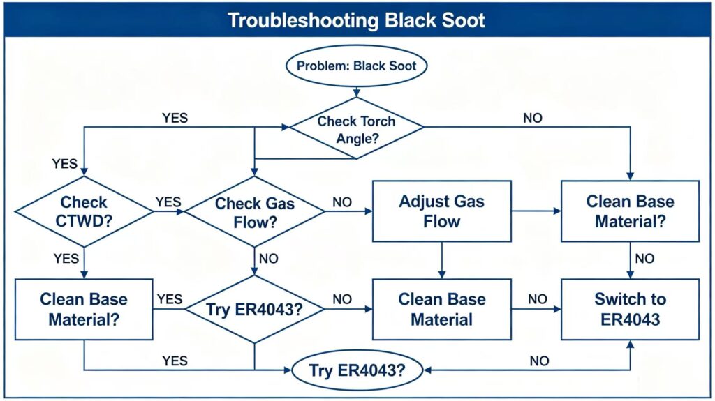
A Quick Troubleshooting Flowchart for Engineers:
Use this decision tree when you see black soot:
Final Summary: What You Need to Remember
Question Answer:
What is the black soot? Oxidized aluminum and magnesium vapor (Al²O³ and MgO)
Why does it happen? Metal vapor touches air before it can solidify
Why robotics? Dead torch angles, CTWD drift, and no adaptive heat control
What is the #1 fix? Change to a 10-15° Push angle
What is the #2 fix? Shorten CTWD to 12-15mm and add a gas lens
When should you switch wire? If ER5356 soot persists and the part is not anodized
How long to test fixes? Run 20-30 parts after each change to verify consistency
Your Next Step:
You now have the engineering playbook for eliminating black soot on robotic aluminum welds.
Pick one solution from this list. Implement it today. Run a test batch. Measure the results.
Then move to the next solution.
Black soot is not a mystery. It is not a “robot problem.” It is a physics problem with engineering solutions.
And now you have them.
—
Need help optimizing your robotic aluminum welding process? Custom Aluminum Welding with Tig Parts. We provide engineering consulting and contract welding services. Contact our team for a process audit.